
The method
Start with the loads, not the feeder.
Traditional voltage-sag mitigation often starts at the feeder: protect the entire production line with one AC-side solution. Wilson PowerTech starts from the loads instead.
Low-power PLCs, sensors and control circuits can use small UPS or DC backup. High-power VFD-driven loads can be evaluated for flywheel support directly at the DC link. Large AC loads that genuinely need bus-voltage restoration can use DVR.
The objective is simple: protect the process without paying to back up power that does not need to be backed up.
Not necessarily. Protect low-power controls with small UPS/DC backup, support high-power VFDs directly at the DC link with short-duration flywheel energy, and use DVR only for loads that genuinely require AC-bus restoration.
Core architecture
One Production Line, Different Loads, Different Protection
A mixed production line may combine all three layers. Non-sensitive loads do not need to be forced into the ride-through capacity, and DVR remains available wherever actual AC-voltage restoration is required.
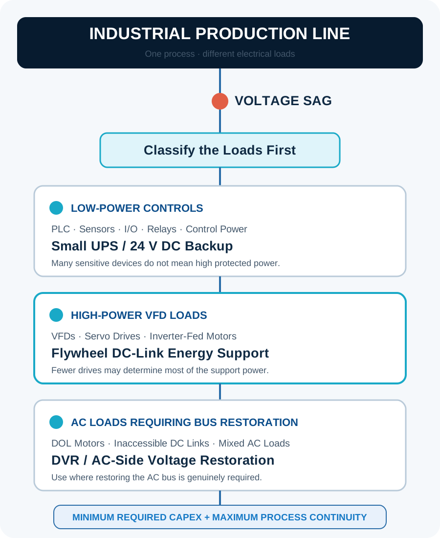
Many control devices can still represent a small combined load.
A few large drives may determine most required ride-through power.
Do not add unnecessary capacity for loads that tolerate the event.
DVR is retained for loads that genuinely require the AC bus.
Sizing boundary
Do Not Size Voltage-Sag Protection from Total Feeder Power Alone
A 2 MW production line does not necessarily require a 2 MW ride-through system. The correct first question is not “How large is the feeder?” It is “Which loads actually cause the process to stop when the voltage sags?”
Illustrative example — not customer data
- Total production-line load
- 2,000 kW
- High-power sag-sensitive VFD loads
- 600 kW
- PLC / sensors / control systems
- 8 kW
- Non-critical or naturally tolerant loads
- 1,392 kW
Protection capacity should follow process-critical loads—not automatically the nameplate power of the entire feeder.
Drive-level energy path
Why Protect a VFD at the DC Link?
A VFD already converts incoming AC power to DC before generating controlled AC for the motor. During a voltage sag, the DC-bus voltage can fall below the drive's undervoltage threshold and trip the process.
Instead of restoring full AC voltage for every upstream load, an external short-duration energy source can support the VFD's DC link directly. A flywheel is especially relevant where high power, short duration and frequent cycling align with the application.
Flywheel remains in standby.
DC support supplies the short-duration energy gap.
Support exits and the flywheel recharges.
Control-power layer
Many Sensitive Devices Are Low-Power Loads
PLCs, sensors, industrial computers, I/O modules, relays and control power supplies may be highly sensitive to voltage sags, but their combined power is often small compared with motors and drives.
These loads can often be supported economically using a small UPS, 24 V DC backup or dedicated control-power ride-through system. Protecting them separately prevents low-power electronics from becoming a reason to install a full-capacity AC-side solution.
Number of sensitive devices is not the same as protected power.
AC-side restoration
When Is a DVR Still the Better Choice?
DVR is a strong starting point when:
- Large induction motors without VFDs must remain energized.
- Critical equipment has no accessible DC link.
- Multiple AC loads require restoration of the actual AC waveform.
- The process specification requires feeder- or bus-level voltage restoration.
- Phase-angle jump, unbalance or deeper AC-side requirements make direct DC support insufficient.
- The customer requires a centralized AC-side mitigation architecture.
Wilson PowerTech does not treat flywheel DC support and DVR as mutually exclusive technologies. The correct architecture depends on the load.
Review WS-DVR AC-side voltage restoration →Selection matrix
Choose the Protection Architecture by Load Type
| Load / Requirement | Preferred Starting Point | Why |
|---|---|---|
| PLC, sensors, I/O, control circuits | Small UPS / DC backup | High sensitivity, low power |
| Large VFD-driven motors | Flywheel DC-link support | Directly supports the energy path that keeps the drive running |
| Servo / inverter-fed processes | DC-side support where compatible | Avoids protecting unrelated upstream load |
| Large DOL induction motors | DVR / AC-side support | Motor requires AC supply |
| Mixed production line | Layered hybrid architecture | Match protection cost to actual load |
| Whole bus must maintain AC voltage | DVR | Bus-level restoration is the requirement |
Project economics
Why the Layered Architecture Can Reduce Total Project Cost
Smaller protected power
Do not size energy support for non-sensitive loads.
Less heavy AC-side modification
DC-side or local protection can reduce the scope of feeder-level rewiring in suitable applications.
Lower installation disruption
Protection can often be implemented by equipment group instead of modifying the whole production feeder.
Modular expansion
Protect the most expensive failure points first, then expand based on measured results.
Preliminary decision tree
Does Your Production Line Really Need a Full-Line DVR?
Use these six questions to identify a starting architecture. The result is not a product selection or final design.
Preliminary architecture
Complete the questions to identify a starting point.
The result distinguishes drive-level DC support, low-power control support and AC-bus restoration. VFD kW is helpful but not required for this first screening step.
Preliminary architecture only. Final design requires voltage-sag records and load data.
Describe the EventEngineering FAQ
Load-Layered Voltage Sag Protection Questions
Do I need a DVR if many devices on my production line are sensitive to voltage sags?
Not necessarily. Many sensitive devices such as PLCs, sensors, I/O modules and relays are low-power loads that can often be protected separately with a small UPS, 24 V DC backup or dedicated control-power support.
The determining factors are the power, electrical architecture and process role of the critical loads—not simply the number of sensitive devices. A load study should identify what trips first and which loads must remain operating together.
Can a flywheel support the DC link of a VFD during a voltage sag?
A short-duration energy source can support a VFD DC link when the incoming AC voltage is too low to maintain the bus. A flywheel can be suitable where the application requires high power, short duration and frequent cycling.
The interface is an engineered connection, not a universal plug-in arrangement. VFD manufacturer limits, DC voltage window, isolation, anti-backfeed protection, precharge, braking behavior, fault coordination and required ride-through time must all be verified.
Why not protect the entire production line with one DVR?
A full-line DVR can be technically appropriate when several AC loads must see restored bus voltage. It may also be the clearest architecture when DC-link access is unavailable or the customer requires centralized feeder-level mitigation.
On a VFD-dominant line, however, full-feeder protection may include non-sensitive or naturally tolerant loads that do not determine process continuity. Classifying the loads first can reduce the protected-power boundary and the associated installation scope.
Is flywheel DC support a replacement for DVR?
No. Flywheel DC support is an alternative or complementary architecture for suitable high-power VFD or inverter-fed loads. It does not restore the AC waveform for unrelated equipment on the feeder.
DVR remains relevant for large non-VFD motors, inaccessible DC links, mixed AC loads and specifications that require feeder- or bus-level voltage restoration. A hybrid project can use both technologies at different load layers.
What loads are best suited to flywheel voltage-sag ride-through?
The strongest starting candidates are high-power VFD-driven or inverter-fed loads that need short-duration, high-power support and have an accessible, approved DC-side interface. Examples may include selected production drives, compressors or pumps after the actual trip mechanism is confirmed.
Suitability still depends on measured sag depth and duration, simultaneous load demand, process inertia, recovery behavior and the VFD's permitted DC-link operating window. Final selection requires site data and OEM review.
What loads still need UPS protection?
PLCs, sensors, industrial computers, network switches, I/O, relays and control power supplies may still require a small UPS, 24 V DC backup or dedicated control-power ride-through system, depending on the electrical design.
Separating these low-power electronics from high-power motor loads prevents the quantity of control devices from unnecessarily increasing the rating of the main ride-through system.
What if my production line has large motors without VFDs?
Large direct-on-line induction motors require an AC supply and cannot be supported through a VFD DC link that does not exist. DVR or another AC-side solution may therefore be the appropriate starting point for those loads.
The study must also consider motor dynamics, contactors, protection settings, voltage recovery and whether the whole bus or only a selected branch must remain energized.
How should voltage-sag protection capacity be calculated?
Capacity should start from the actual critical-load power and the protection boundary—not automatically from the total feeder nameplate. The study should include sag depth, duration, phase behavior, required ride-through time and the sequence of equipment trips.
For DC-link support, engineers must also check DC voltage limits, motor demand, process inertia and recovery requirements. For DVR, the required injected voltage, active-energy contribution, overload behavior and AC-bus performance must be evaluated.
Continue the engineering review